Step 2: Drilling the Gate
Gate Drill
- First drill G1. This hole is drilled on a Light Lean angle toward the direct center of the gate. Next, slide your drill guide over G2 and drill the same Light Lean toward the center of the gate. See Fig. 7 & Fig. 7b. Then clean out the debris and sleeve the hole Fig. 7c & 7d.

NOTE: Refer to D.I.Y. Install Guide for Lean Settings on the Drill Guide Light Lean Light Lean or call 561-316-6418 - Drill G3 on a Light Lean toward the direct center of the gate. Next slide the drill guide over G4 and drill the same lean as G3 See Fig. 8 & 8b. Then clean out the debris and sleeve the hole Fig. 8c & 8d.

- Drill L1 & R1 Level when the gate is going in a straight line.
- Please Call 561-316-6418 if you have any questions
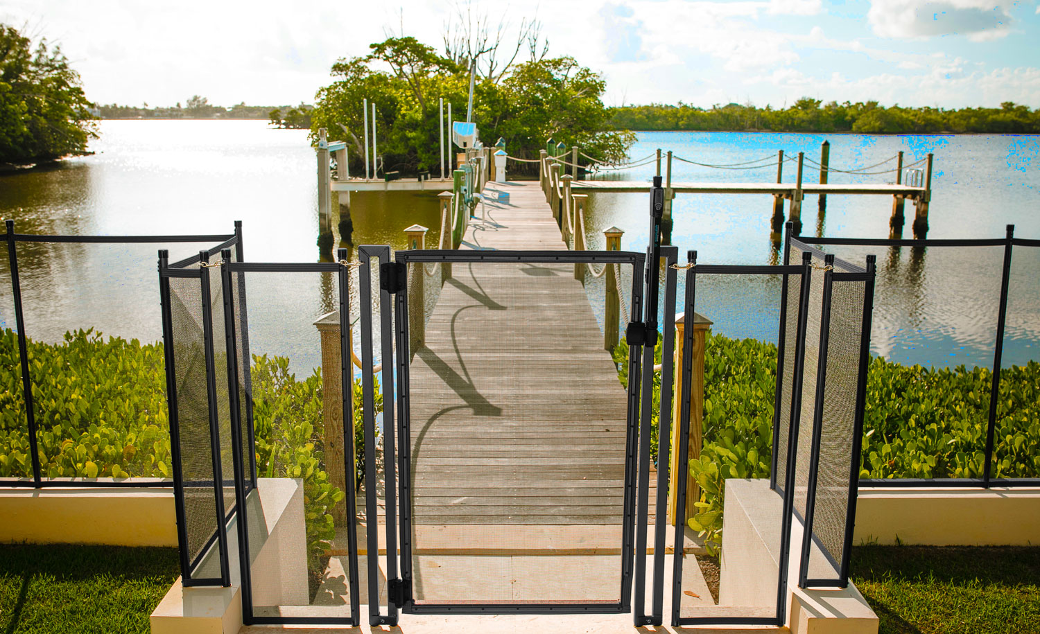
Gate Assembly Instructions
****NOTE: There are 2 upright posts, one has pre-drilled holes for the hinges the other has pre-drilled holes for the latching system.****

-
Lay Out:
Lay the Gate Frame gate from scratching. ***NOTE: You can use the box the gate is shipped in. -
Attach Hinges:

To attach the hinges you must first find your upright post that has the pre-drilled holes at the top and bottom, make sure that the allen key used to adjust the tenson for the hinge is facing upwards so the holes align, the hinges can be mounted to have the gate open either direction. Once aligned use the Hex head hinge screws provied to attach the hinges as shown.

-
Attaching Mounting Bracket and Striker Body:

NOTE: Separate the Latch body locking screw from the rest of the mounting screws, it will be slightly longer. This screw is used for completion and will be the final step of adjusting your gate.

The mounting bracket for the striker body will attach on the square mesh portion of the gate, find the pre-drilled hole located on the side, you may have to remove one screw holding the moulding to align the bracket. Drill new holes if location is not ideal. Once the bracket is attached the striker body will slide onto the bracket -
Set Latch Body Mounting Plates:
Once you have attached the mounting bracket and the striker body to the mesh frame you will attach the latch body to the upright post for the latch hardware as shown in diagram. The two brackets provided with the latch body need to be removed from it by sliding them off the bottom of the latch body, once removed place the brackets over the pre-drilled holes on the latch uprights, the bottom bracket will align with the striker body as shown in the diagram. When attaching the brackets do not screw in the bottom screw, this will be for the latch body mounting screw and will be the very last step you will do.

-
Attaching Latch Body:
Once the brackets are attached to the latch upright you can then slide the latch body onto its brackets the very bottom hole will be for final adjustments and to lock your latch body in place.


Gate Latch Installation

Gate Hinge Installation
Latching the Gate
NOTE: YOU MAY NOT NEED ATTACH THE LATCHES IF THEY ARE ALREADY ATTACHED
- Drill the pilot hole and bevel Fig. 11. Then screw your latch in as shown in Fig. 11b.


- Now place a small level on top of the gate. This will allow you to put the other part of the latch in the correct place so that the gate will be level when latched. See Fig. 12
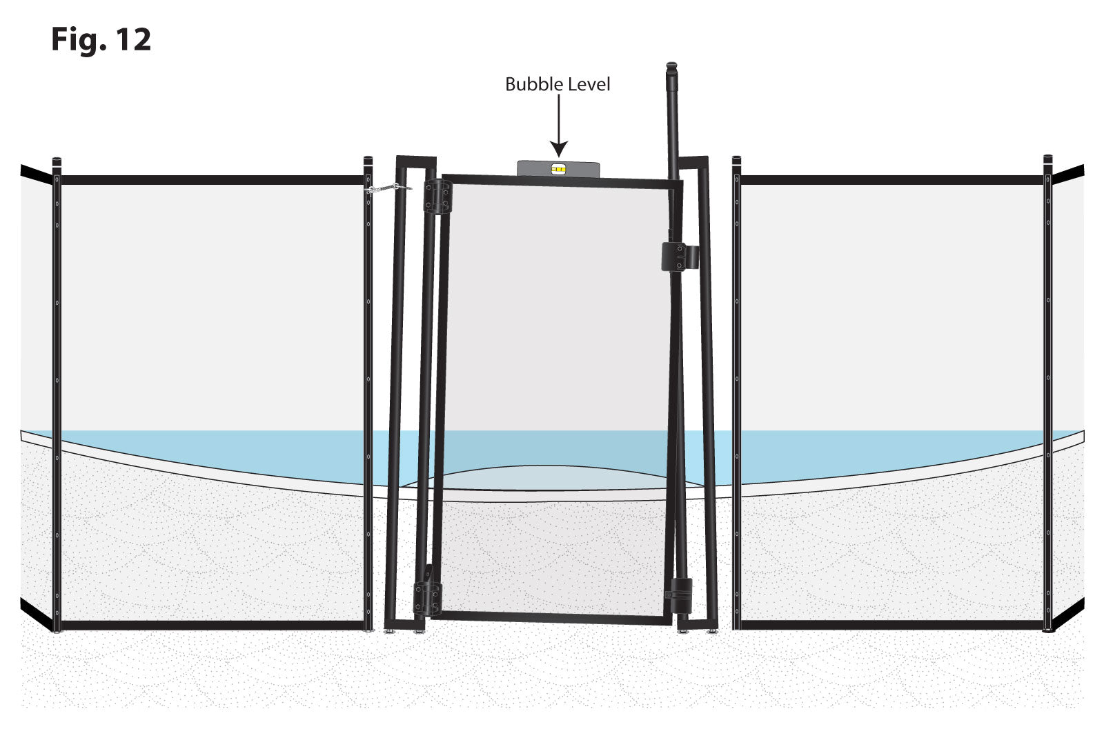
- Squeeze fence post L1 and the gate frame as shown below in Fig.13 until the bubble indicates level. Then make a mark on the Gate Frame Post where to drill for the part of the latch. Please Call 561-316-6418 if you have any questions.

NOTE: YOU MAY NOT NEED TO DRILL HOLES, THEY COULD BE PRE-DRILLED, DRILL NEW HOLES ONLY IF YOU CANNOT GET GATE LEVEL - Using your drill gun and the 1/8" drill bit, drill the hole in the Gate Frame post where you marked and bevel. See Fig. 14. Now disconnect the latch from the screw eye and turn the other screw eye into the Gate Frame Post using the latch to turn it until there are no visible threads.


- Squeeze Pole L1 and the Gate Frame Post and connect the latch to the screw eye. The bubble should indicate level when the latch is connected as shown below. See Fig. 15

- Next using your drill and 1/8" drill bit, drill through pilot hole in pole R1 and bevel. See Fig. 16. Then screw your latch into the hole you just drilled into pole R1 Fig. 16a


- This post should also be level. Squeeze R1 and the Latch Post until the latch post is level hen mark where to drill. See Fig. 17. Next, using your drill with the 1/8" drill bit, drill a hole into the front of the Latch Post and bevel. See Fig. 17a. Disconnect the latch from Pole R1 and screw it into the Latch Post. See Fig. 17b. Now squeeze the Latch Post and Pole R1 and connect using the latch you just installed.


***NOTE: YOU MAY NOT NEED TO DRILL HOLES, THEY COULD BE PRE-DRILLED IF THE PRE-DRILLED HOLES DO NOT ALLOW THE GATE TO BE LEVEL, DRILL THE HOLES IN THE PROPER POSITON TO ACHIEVE A LEVEL GATE OR GATE POST. - The D.I.Y. Gate is connected to the fence. See Fig. 18. You now must make all necessary adjustment to the D.I.Y. Gate Latch System and Hinges. There are 3 areas you will most likely need to adjust. Area 1 is the Latch Body. Area 2 is the striker body. Area 3 are the Hinges.

- In Fig. 19 shows how to lock down your Latch body once final adjustments have been made.
- Start with Area 1 (Latch Body) to adjust. There is a locking screw located on the bottom of the latch body. Remove the locking screw and slide the Latch Body either up or down on its track and line it up to the catch. See Fig. 19 In this example the Latch Body must slide down until the Locking Pin is just below the top of the Catch as shown in Fig. 19a then replace the locking screw.


- Fig. 20 shows how to make horizontal adjustments. Fig 20A shows how the 2 parts should line up for proper latching.
- Area 2 (Catch) must be adjusted in this example to meet the Latch Body. Using a Philips Head screw driver turn the Catch Adjustment Screw counter clockwise so that the Catch will slide out to meet the Latch Body as shown in Fig. 20. When the correct amount of adjusting is done, the Catch should meet the Latch Body and lock smoothly as shown in Fig. 20a.


- Area 3 (Hinges) are adjusted in order to give the D.I.Y. Gate its signature self closing feature. Both Hinges should be adjusted equally. Simply use a flat head screw driver on either the top or the bottom of the each hinge (Depress and turn counter-clockwise to increase tension on the top of each hinge; or by depressing and turning clockwise increase tension on the bottom of each hinge.) Test tension on gate by opening it and watching it swing closed. Do this to both Hinges until desired tension is aquired. Then replace slip cap on the bottom hinge. For more info, please call 561-316-6418
Design Your Own Pool Fence
Calculator Step 1 of 14
Installing a Complete or Partial Fence?
Will your fence go completely around the pool, or will you be attaching it to an existing wall or barrier?
Fence will go completely around the pool
Fence will be attached to existing fence or wall


Calculator Step 2 of 14
Fence Height
($9.88 / foot)

*MOST POPULAR*
($15.33 / foot)

*Meets California code*
Calculator Step 3 of 14
Fence Color


Calculator Step 4 of 14
Total Fence Length
What is the total length in feet you will need for your fence?
If your fence will be completely in a hard surface, e.g. concrete, thick wood, tiles over concrete or a hard subsrate, stone, etc., leave the number of feet over grass as "0" and vice versa.
If your fence will be partly in a hard surface and partly in grass, enter the total number of feet of fence you will need in each surface into the two fields below.
Calculator Step 5 of 14
Arched or Flat Top Gate
Your self-closing gate can either have the standard flat top or be upgraded to an arched top.

Calculator Step 6 of 14
Self-Closing, Self-Latching Gates
How many self-closing, self-latching gates would you like?
Gates that will be in a hard surface
Gates that will be in grass/dirt
The Pool Fence DIY system includes a manual opening at no charge. Self-closing, self-latching gates are recommended by everyone from the American Academy of Pediatrics to the Consumer Product Safety Commission to the National Drowning Prevention Alliance. Besides being safer, they are also MUCH more convenient. A must if you have older children who use the pool.
Calculator Step 7 of 14
90° Turn Posts
Are you making any 90° turns? If yes, how many?

Calculator Step 8 of 14
Accessories
This item is HIGHLY recommended to ensure the fence is properly installed.
Will you need the Pool Fence DIY Drilling Guide with Bubble Level?
$0.00 $122.56

Calculator Step 9 of 14
Rotary Hammer Drill
The Pool Fence DIY Rotary Hammer Drill is the recommended hammer drill for installing this style of mesh pool fencing. Having the right tool for the right job makes installation go smoother. It also comes with a 16" long x 5/8" diameter drill bit, which is the recommended bit for this installation and is the correct length for the Pool Fence DIY Drill Guide, which is highly recommended.
$217.99 $173.61
Sorry, item currently out of stock.

Calculator Step 10 of 14
Drill Bits
Do you need the correct bit for your hammer drill (or an extra bit)?
Pool Fence DIY SDS-Plus Masonry Bit 5/8th Inch Diameter by 16 Inch Length (compatible with the Pool Fence DIY Rotary Hammer Drill)
Pool Fence DIY Standard (Smooth Shank) Masonry Bit 5/8th Inch Diameter by 16 Inch Length (for non-SDS compatible hammer drills)
$21.98 each

$21.35 each

Calculator Step 11 of 14
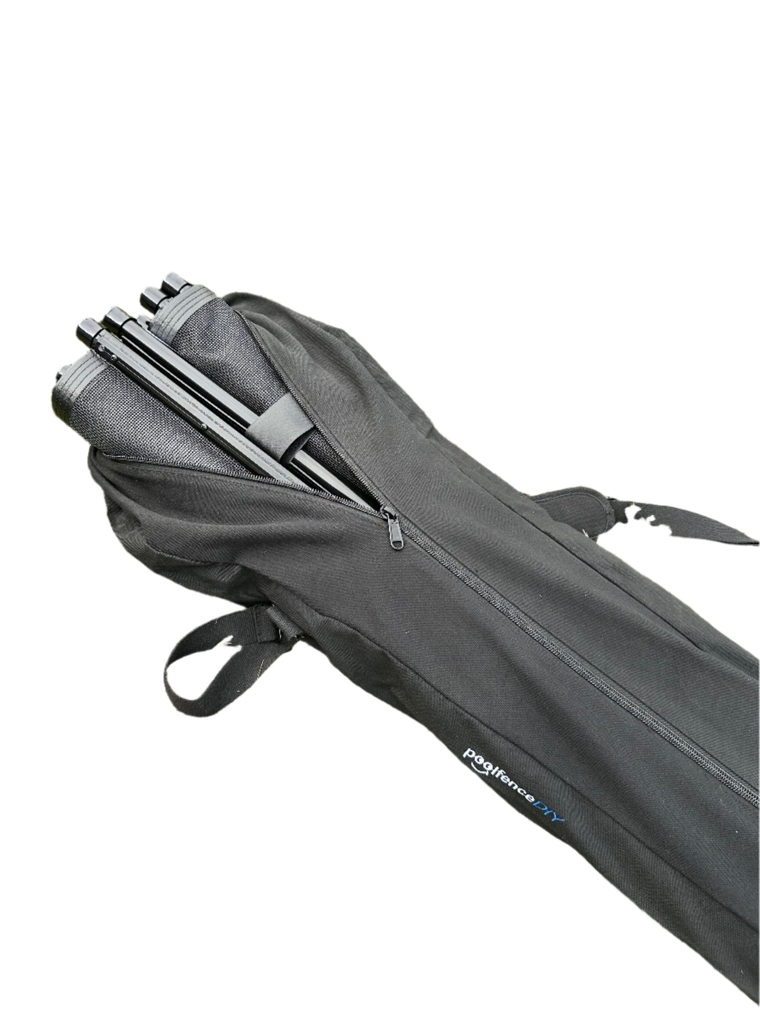
Do you want storage bags for your fence sections?
Our Pool Fence Section Storage Bag offers a reliable and convenient way to store and transport your fence sections. Each bag is designed to hold two 4-foot sections and includes two smaller straps to wrap each section securely, keeping everything compact and ready for storage. Made from heavy-duty canvas with a strong zipper, this bag is built for durability. Rubber pads on the bottom prevent canvas wear and slipping when the bag is stood on end. With a comfortable shoulder strap for easy carrying, this storage bag is an ideal choice for off-season storage or anytime your pool fence is not in use.
$39.00 each
Sorry, item currently out of stock.
Calculator Step 12 of 14
How many Solar Lights do you want on your fence?
$10.22 each
Quantity:


Calculator Step 13 of 14
Do you want to add Omni-Hangers to your fence?
How many two-packs you would like with your fence?
$25.24 per two-pack
Quantity:

